

As a software engineer, I'm used to having fully automated every step of the deployment process and reducing the manual input as much as possible. There is just something so satisfying about clicking a button and watching it doing all the work.
But for my weather station project, this seemed not possible. When I started with this project, I used KiCad 6 with an unversioned directory on my development machine and started designing. I frequently made mistakes or broke parts of the schematic - so I needed some way of being able to roll back and tagging releases. This was also important when I ordered PCBs - without tags it is hard to link your order to the iteration of your KiCad project. So it was time to implement CI for KiCad!
All beginnings are rough
Initially, I started searching the internet for tools that would help me with this. I wanted a simple pipeline, that performs the DRC and ERC, generates images of the schematic, individual layers and a combination of all layers, a BOM (bill of material) and the production files required to send the project to a manufacturer.
At first, I didn't find any applications or tools, that could do this in a headless environment (e.g. the GitHub actions). But then, I came across the KiPlot project, which seemed to exactly do what I wanted:
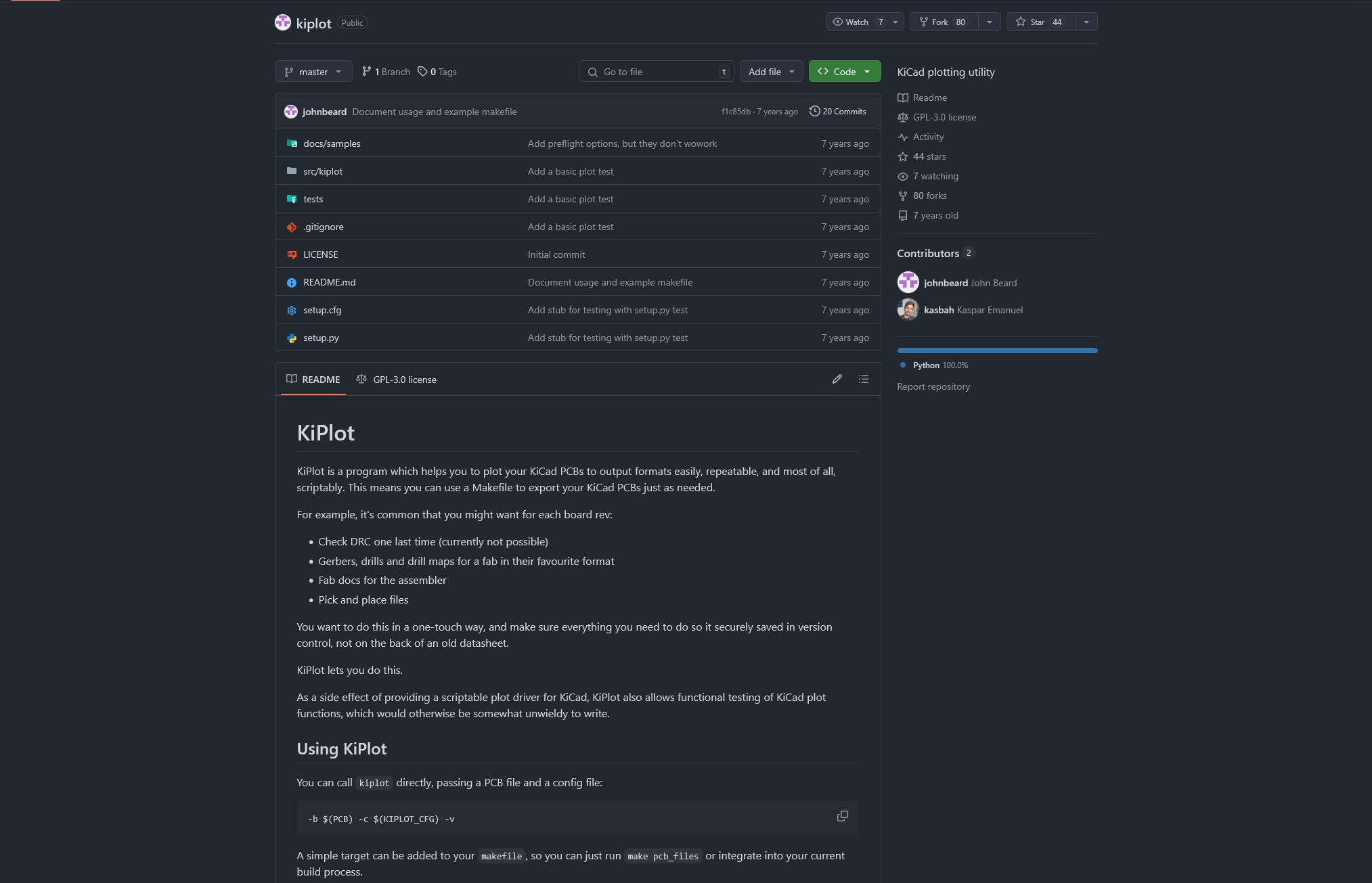
All hopes are quickly shattered though, if the last commit was 7 years ago. when KiCad 7 wasn't even on the horizon. Soon after, I found KiBot, which is an active maintained fork of the original project - and it's compatible with KiCad 7!
And thanks to the maintainers of this project, it even runs in headless environments and doesn't require a dedicated GPU to render images.
Working with Git and KiCad
Next, I needed a git server to push my version controlled files. But would git even be suitable for this? Turns out the KiCad files are just text files with their own file extensions, such as .kicad_sch:
(kicad_sch
	(version 20250114)
	(generator "eeschema")
	(generator_version "9.0")
	(uuid "3e093a46-43d3-4239-969a-ffefe6fd6b27")
	(paper "A4")
	(lib_symbols
		(symbol "Connector:6P6C"
			(pin_names
				(offset 1.016)
			)
			(exclude_from_sim no)
			(in_bom yes)
			(on_board yes)
			(property "Reference" "J"
				(at -5.08 11.43 0)
				(effects
					(font
						(size 1.27 1.27)
					)
					(justify right)
				)
			)
Perfect, so I created a local repository and pushed it to GitHub. Now let's tackle the CI.
Building the CI
First, it should be noted that there are different variants & versions of the KiBot available. They are all based on Debian and only work with the matching major version of KiCad - meaning that KiBot 7 won't work with KiCad 8.
There's the auto_full images and the autoimages. The full images contain additional dependencies, such as LaTeX and Blender, which can be useful if you want certain outputs - more on this later.
To start, I simply copied the GitHub actions workflow in the documentation to my private repository:
name: Run KiBot

on:
  push:
    paths:
    - '**.sch'
    - '**.kicad_pcb'
  pull_request:
    paths:
      - '**.sch'
      - '**.kicad_pcb'

jobs:
  example:
    runs-on: ubuntu-latest
    steps:
    - uses: actions/checkout@v2
    - uses: INTI-CMNB/KiBot@v2_k7
      with:
        config: config.kibot.yaml
        dir: output
        schema: 'schematic.sch'
        board: 'pcb.kicad_pcb'
    - name: upload results
      if: ${{ always() }}
      uses: actions/upload-artifact@v4
      with:
        name: output
        path: output
And because I didn't read the documentation at first, I didn't understand that I needed to create a configuration file too, which defines how KiBot should process the KiCad files and what outputs to generate.
I started adding a few simple outputs that I definetly need, such as the IBoM:
kiplot:
  version: 1

preflight:
  run_erc: true
  update_xml: true
  run_drc: true
  check_zone_fills: true
  ignore_unconnected: false

global:
  units: millimeters

outputs:
  - name: iBoM
    comment: Interactive HTMl BoM
    type: ibom
    dir: assembly/interactive-bill-of-materials/
    options:
      highlight_pin1: true
      checkboxes: "Placed"
      dark_mode: true
Running this workflow would start KiBot and upload the results as artifacts to the GitHub actions run - perfect!
Time to add more outputs
Since the basic concept of the workflow worked now, I started adding more outputs to the config:
kiplot:
  version: 1

preflight:
  run_erc: true
  update_xml: true
  run_drc: true
  check_zone_fills: true
  ignore_unconnected: false

global:
  units: millimeters

outputs:
  - name: iBoM
    comment: Interactive HTMl BoM
    type: ibom
    dir: assembly/interactive-bill-of-materials/
    options:
      highlight_pin1: true
      checkboxes: "Placed"
      dark_mode: true
+ - name: 'print_sch'
+   comment: "Print schematic (PDF)"
+   type: pdf_sch_print
+   dir: schema/
+   options:
+     output: full_schematic.pdf
+ - name: 'print_sch_svg'
+   type: svg_sch_print
+   dir: schema/images
+   comment: "Generate SVG from schematics"
+   options:
+     monochrome: false
+     all_pages: true
+     background_color: true
+     output: "%I.%x"
+     frame: false # do not include frame and title block
+ - name: 'print_front'
+   comment: "Print layer 1"
+   type: pdf_pcb_print
+   dir: pcb/layers/
+   options:
+     output_name: layer_1.pdf
+   layers:
+     - layer: F.Cu
+ - name: 'print_back'
+   comment: "Print layer 4"
+   type: pdf_pcb_print
+   dir: pcb/layers/
+   options:
+     output_name: layer_2.pdf
+   layers:
+     - layer: B.Cu
+ - name: basic_position_CSV
+   comment: Components position for Pick & Place
+   type: position
+   dir: positions/csv
+   options:
+     format: CSV
+     only_smd: false
+     output: '%i %f_pos_%D.%x'
+ - name: basic_render_3d_0deg_top
+   comment: 3D view from 0 degrees top
+   type: render_3d
+   dir: renders/top
+   output_id: _view
+   options:
+     output: '%f-%i%I%v-0deg.%x'
+     ray_tracing: true
+     rotate_x: 0
+     rotate_z: 0
+     download: true
+     height: 1440
+     width: 2560
+     no_virtual: true
+ - name: basic_render_3d_30deg_top
+   comment: 3D view from 30 degrees top
+   type: render_3d
+   dir: renders/top
+   output_id: _view
+   options:
+     output: '%f-%i%I%v-30deg.%x'
+     ray_tracing: true
+     rotate_x: 3
+     rotate_z: -1
+     download: true
+     height: 1440
+     width: 2560
+     no_virtual: true
+ - name: basic_render_3d_0deg_bottom
+   comment: 3D view from 0 degrees bottom
+   type: render_3d
+   dir: renders/bottom
+   output_id: _view
+   options:
+     output: '%f-%i%I%v-0deg.%x'
+     ray_tracing: true
+     rotate_x: 0
+     rotate_z: 0
+     download: true
+     view: bottom
+     height: 1440
+     width: 2560
+     no_virtual: true
+ - name: basic_render_3d_30deg_bottom
+   comment: 3D view from 30 degrees bottom
+   type: render_3d
+   dir: renders/bottom
+   output_id: _view
+   options:
+     output: '%f-%i%I%v-30deg.%x'
+     ray_tracing: true
+     rotate_x: 3
+     rotate_z: -1
+     download: true
+     view: bottom
+     height: 1440
+     width: 2560
+     no_virtual: true
+ - name: step
+   type: step
+   comment: Export the PCB as a 3D model
+   dir: 3d_models/step
+ - name: position
+   type: position
+   dir: positions/pos
+   comment: Positions for components
+ - name: virtualRealityModelLanguage
+   type: vrml
+   dir: 3d_models/vrml
+   comment: VRML 3d model
+   options:
+     download: true
This created the following file tree:
- schema/
- images.png
- full_schematic.pfg
- images/
- sheet-1.svg
- sheet-2.svg
- 3d_models/
- step/
- model-3D.step
- step/
- vrml/
- model-vrml.wrl
- shapes3D/
- XXXX.wrl
- assembly/
- interactive-bill-of-materials/
- project-ibom.html
- interactive-bill-of-materials/
- pcb/
- layers/
- layer_1.pdf
- layer_2.pdf
- layers/
- positions/
- csv/
- top_pos_project.csv
- bottom_pos_project.csv
- pos/
- top_pos_project.pos
- bottom_pos_project.pos
- csv/
- renders/
- top/
- project-3D_top-view-30deg.png
- project-3D_top-view-0deg.png
- bottom/
- project-3D_bottom-view-30deg.png
- project-3D_bottom-view-0deg.png
- top/
The resulting ZIP archive, uploaded to the GitHub artifacts, was about 12-16MB. But there was one issue with the file formats of some of the files - when sending them for review to friends or forums, I prefer to upload JPEG or PNG pictures instead, because PDFs aren't widely used and can embed malicious code.
So I updated my workflow file to convert SVG to PNG and PDF to PNG using Inkscape:
+     - name: Install Inkscape
+       run: sudo apt-get install -y inkscape

      - name: Checkout Code
        uses: actions/checkout@v4

      - uses: INTI-CMNB/KiBot@v2_k7
        with:
          config: config.kibot.yaml
          dir: output
          schema: 'schematic.sch'
          board: 'pcb.kicad_pcb'

+     - name: Convert SVG to PNG
+       run: |
+         for svg_file in $(find ./output/schema/images/ -type f -name "*.svg"); do
+           png_file="${svg_file%.svg}.png"
+           sudo inkscape -d 400 "$svg_file" -o "$png_file"
+         done

+     - name: Convert PDF to PNG
+       run: |
+         for pdf_file in $(find ./output/pcb/layers/ -type f -name "*.pdf"); do
+           png_file="${pdf_file%.pdf}.png"
+           sudo inkscape -d 300 "$pdf_file" -o "$png_file"
+         done

      - name: upload results
        if: ${{ always() }}
        uses: actions/upload-artifact@v4
        with:
          name: output
          path: output
Leveraging the matrix 😎
As my project grew, I start splitting modules of the PCB into their own project, since KiCad recommends to only have one PCB per project.
This also required my workflow to be able to handle multiple project files.
GitHub has a great system for this: https://docs.github.com/en/actions/writing-workflows/choosing-what-your-workflow-does/running-variations-of-jobs-in-a-workflow#using-a-matrix-strategy.
So let's implement it in the workflow:
jobs:
  run-kibot:
    runs-on: ubuntu-latest
    strategy:
      matrix:
        module:
          - name: motherboard
            config: pcbs/motherboard/config.kibot.yaml
            dir: motherboard-outputs
            schema: pcbs/motherboard/motherboard.kicad_sch
            board: pcbs/motherboard/motherboard.kicad_pcb
          - name: module-temperature
            config: pcbs/modules/temperature/config.kibot.yaml
            dir: module-temperature-outputs
            schema: pcbs/modules/temperature/module_temperature.kicad_sch
            board: pcbs/modules/temperature/module_temperature.kicad_pcb
Then, we reference the variables in the steps that will be dynamic depending on the project:
      - name: Run KiBot
        uses: INTI-CMNB/KiBot@v2_dk9
        with:
          config: ${{ matrix.module.config }}
          dir: ${{ matrix.module.dir }}
          schema: ${{ matrix.module.schema }}
          board: ${{ matrix.module.board }}
And let's adjust the upload too, so we don't overwrite the archives with each other:
      - name: Upload Outputs
        uses: actions/upload-artifact@v4
        with:
          name: ${{ matrix.module.name }}-outputs
          path: ${{ matrix.module.dir }}
Conclusion
It seems that Git is capable enough to handle KiCad projects and they can be especially useful if you are used to software development. The GitHub workflow I presented you today shows, that automating is also possible and you could even order PCB automatically.
I think such workflows could be really useful to small projects, where only a few people are involved with the development of a PCB and software for it. Scaling up will be hard, since manually resolving merge conflicts in the KiCad files will be tedious and prone for failure. Another problem could be the runners and data space on GitHub; rendering 3D images with ray tracing takes up to 2 minutes per image on my project, because it is CPU bound. Using a graphic card would speed up the render significantly. And since every run creates between 5 and 20 MB of artifacts, storage on the free GitHub version will fill up quickly. It might be worth it to consider uploading to external storage or pay for additional storage.
Personally, I'm very satisfied with this solution and will continue to use it in my projects. What do you think? Have you used KiCad yet?


Member discussion