Information
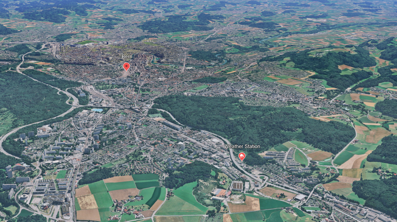
The weather station is located near Bern and is exposed to a windy spot. It consists of multiple sensors and pushes data every few seconds using WLAN via ESPHome to HomeAssistant. Using an InfluxDB adapter, the data is then pushed to a time series database, which is consumed by Grafana and visualized as above.
The goal of this project is to publish independent data and learn how to design PCBs for myself. I collect whatever data interests me and visualize them here for the public.
2022: Iteration 1
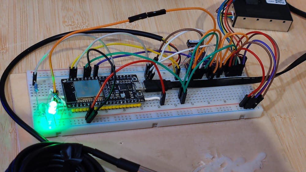
This was the first-ever iteration of the project. It served as a minimal proof of concept and to collect experience with the ESP32 microcontroller, since I haven't had much experience with it back then. It used breadboard jumper cables and several external sensors, such as the SEN54 and the DS18B20.
2022: Iteration 2
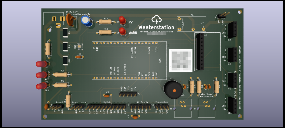
For the next iteration, I started learning how to design PCBs using KiCad and how to order them online. Essentially, I copied the schematic of the breadboard prototype to the schematic editor of KiCad and chose fitting footprints.
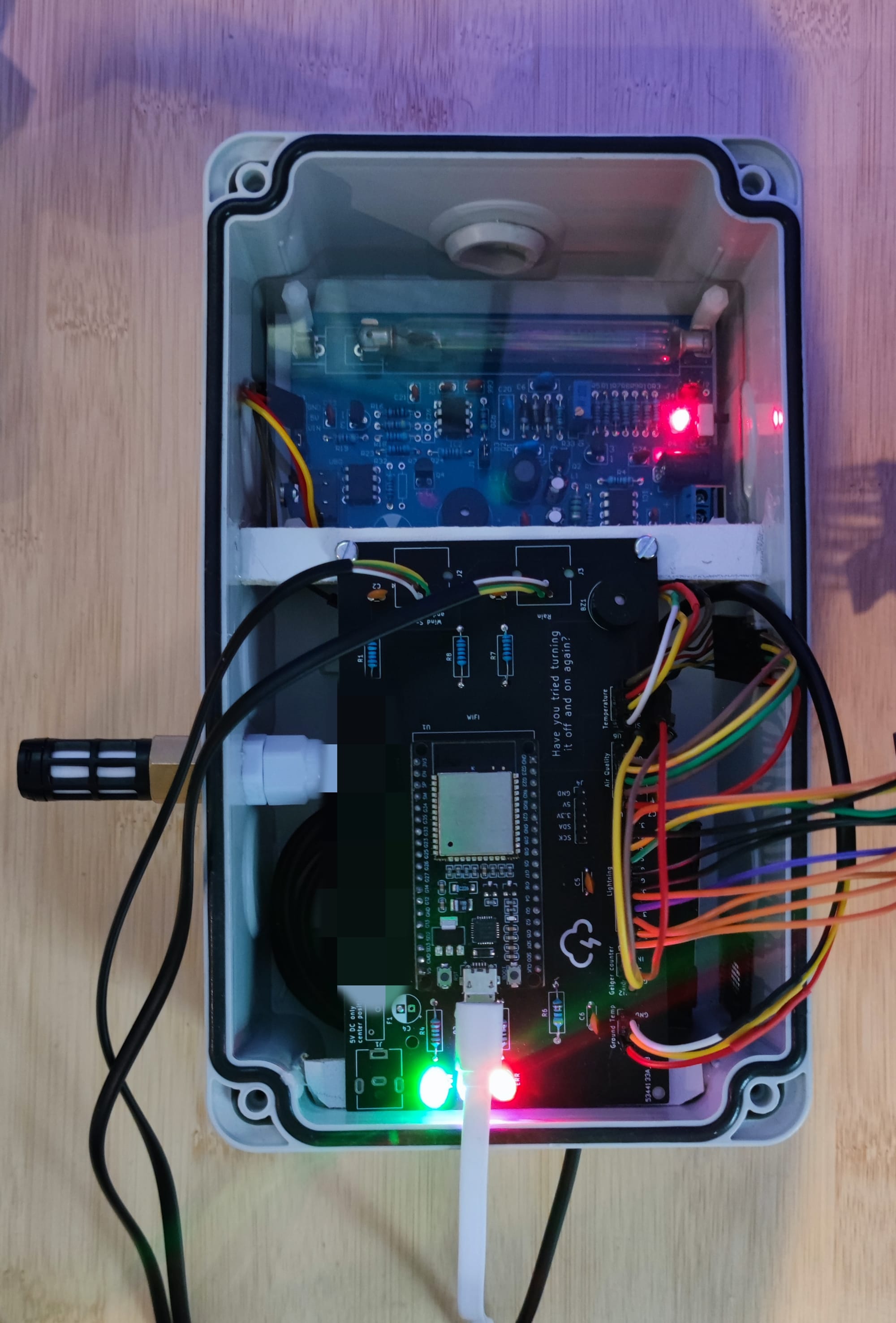
As you can see, I still used breadboard cables and external sensors, which often led to unstable connections and sensors not reacting reliabily. This iteration was also the first one, where I started experimenting with weatherproof enclosures. Even though Iteration was outside too for multiple months, this version was the first to be in a location without any artificial protection from the weather.
From the picture another problem is also apparent: some footprints I chose were completly wrong and two traces were not correct, so I had to do trace repair.
2023: Iteration 3
The next iteration only fixed some incorrectly routed traces, added some additional connectors, added a relay for a fan and added power measurements for the entire PCB. This iteration was short lived, because it still had some of the issues of iteration 2. This was also the year that I moved and had a lot of private things going on, so I didn't focus on this project.
2024: Iteration 4
As for my next iteration, I knew that I wanted to get rid of the long standing issues, such as unstable connections, wrong footprints and wanted to add more security features, such as fuses and diodes.
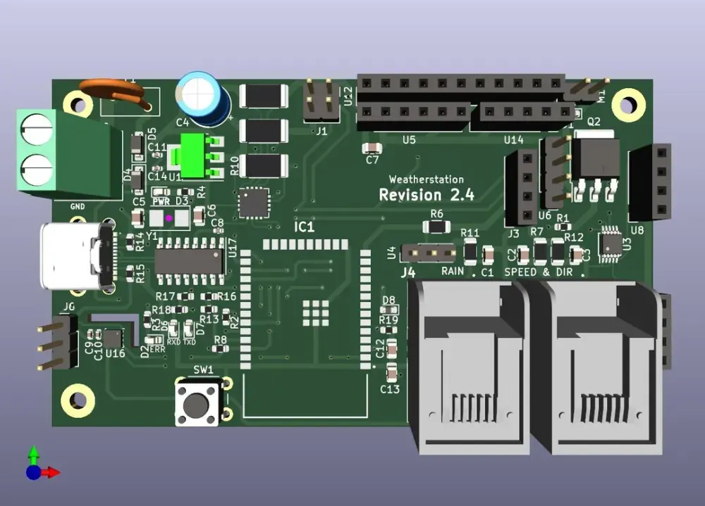
One big change here was, that I now used SMD (surface mounted components) instead of the previously used THT (through hole components). This led to a smaller overall size of the PCB which also forced me to more carefully design the PCB. It was also the first version, where I no longer used a consumer-oriented ESP32 module, but directly mounted an ESP to my PCB and designed the flashing circuit around it.
These were really my first experiences with SMD - so let the manufacturer assemble most of the hard components and chose easy to solder components.
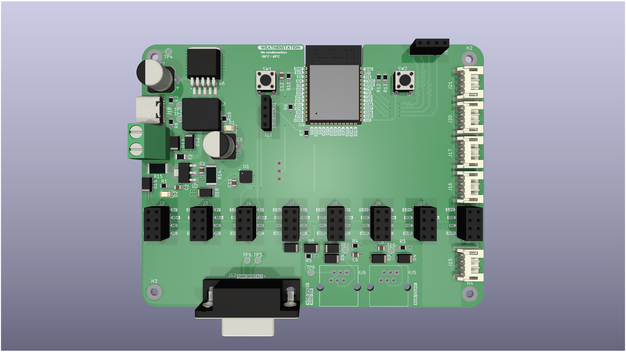
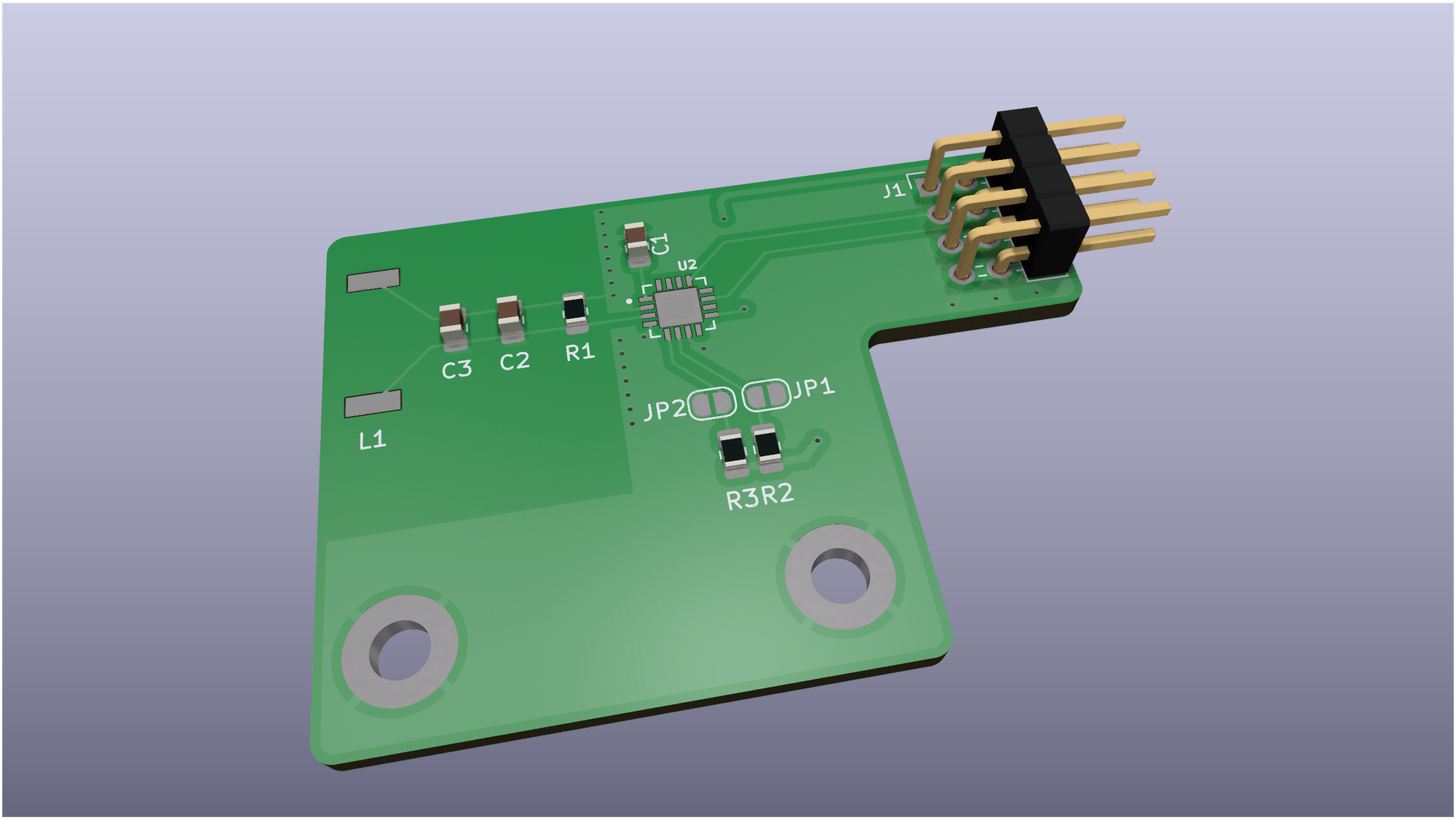
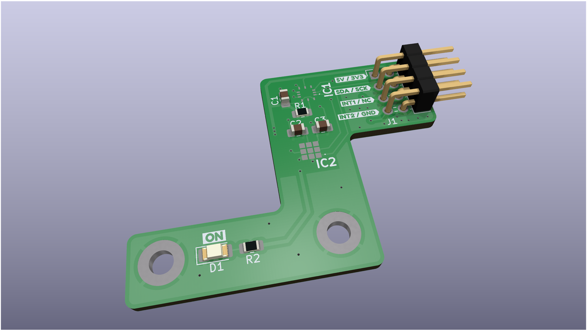
2025: iteration 5
In 2025, I started moving my sensors to modules, so I can reuse them between iterations of the PCB. Additionally, I added more connectors and better suited IO. I also created my first own 5V buck converter with the LM2595S-5. I also swapped the ESP32 WROOM 32E with the ESP32 S3 WROOM 1, which has a built in UART controller for direct USB connection, which reduced cost by about 4 dollars per PCB.